|
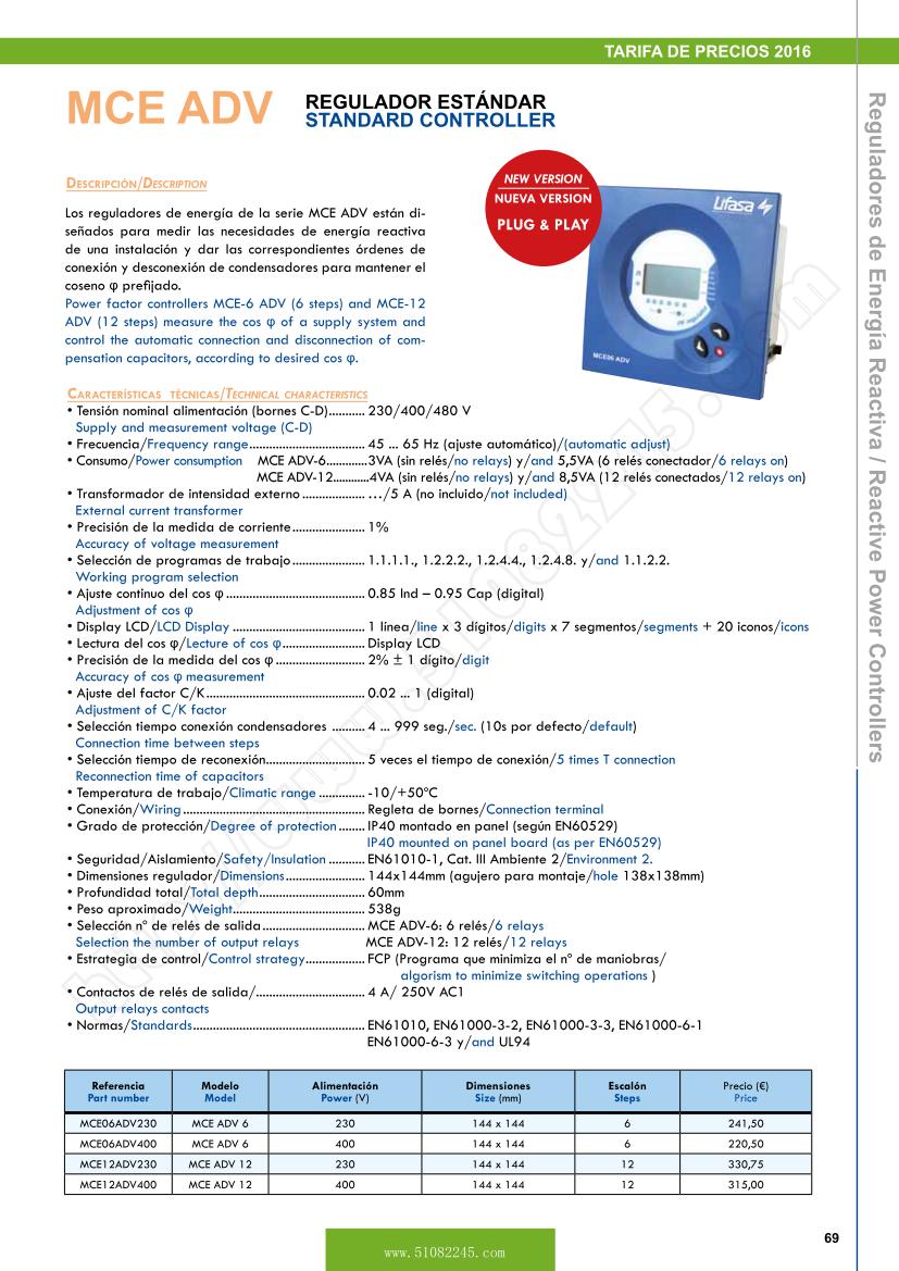
MCE ADV STANDARD CONTROLLER
Description
Power factor controllers MCE-6 ADV (6 steps) and MCE-12 ADV (12 steps) measure the cos �� of a supply system and control the automatic connection and disconnection of compensation capacitors, according to desired cos ��.
Technical Characteristics
Supply and measurement voltage (C-D) ........... 230/400/480 V
- Frequency range ................................... 45 ... 65 Hz (automatic adjust)
Power consumption MCE ADV-6 .............3VA (no relays) y/and 5,5VA (6 relays on)
MCE ADV-12............4VA (no relays) y/and 8,5VA (12 relays on)
External current transformer ................... ��/5 A (not included)
Accuracy of voltage measurement ...................... 1%
Working program selection ...................... 1.1.1.1., 1.2.2.2., 1.2.4.4., 1.2.4.8. y/and 1.1.2.2.
Adjustment of cos ��.......................................... 0.85 Ind �C 0.95 Cap (digital)
LCD Display ........................................ 1 line x 3 digits x 7 segments + 20 icons
Lectura del cos ��/Lecture of cos �� ......................... Display LCD
Accuracy of cos �� measurement ........................... 2% �� 1 digit
Adjustment of C/K factor ................................................ 0.02 ... 1 (digital)
Connection time between steps .......... 4 ... 999 sec. (10s default)
Reconnection time of capacitors .............................. 5 times T connection
Climatic range .............. -10/+50oC
Wiring ....................................................... Connection terminal
Degree of protection ........ mounted on panel board ( )
Safety/Insulation ........... , Cat. III Ambiente 2/Environment 2.
Dimensions ........................ 144x144mm (hole 138x138mm)
Total depth ................................ 60mm
Weight ........................................ 538g
Selection the number of output relays.......................MCE ADV-12: 12 relays
Control strategy .................. FCP (algorism to minimize switching operations )
Output relays contacts................................. 4 A/ 250V AC1
Standards ....................................................
Part number |
Model |
Power (V) |
Size (mm) |
Steps |
Price(�) |
MCE06ADV230 |
MCE ADV 6 |
230 |
144x144 |
6 |
241,50 |
MCE06ADV400 |
MCE ADV 6 |
400 |
144x144 |
6 |
220,50 |
MCE12ADV230 |
MCE ADV 12 |
230 |
144x144 |
12 |
330,75 |
MCE12ADV400 |
MCE ADV 12 |
400 |
144x144 |
12 |
315,00 |
Plug and Play
A series of parameters must be configured when a power factor regulator is installed, to make sure that it operates correctly. Some of these parameters might be hard to know, such as, for example, the voltage phases or the voltage corresponding to the current measured, as well as the current transformer ratio. MCE ADV has been designed with a smart automatic process that detects the necessary parameters, such as:
C/K: calculates the ratio of the current transformer and the power of the smallest step.
Phase: Identifies the voltage sequence and correspondence with current. In other words, it identifies the UL1, UL2, UL3, when the current measured is IL1, IL2, IL3 and whether it is connected in the opposite way or not.
Number of stages installed and Program: the system connects all stages in a sequence, finds out how many stages are installed and then calculates the program, i.e., the power ratio of the capacitors.
FEATURES
1. i Mproved setting up configuration when commissioning Phase
Installation and polarity of the CT (Current Transformer). This controller avoids user to switch phases and polarity (cabling) of CT (X/5) connection. Now, user can adjust it and set it up through display menu on the MCE ADV; indicating what phase it is installed and the polarity of the CT.
2. v alues / Measures in the network
- Current (A)
Total RMS current (A) measured from the CT (X/5).
- Voltage (V)
Phase RMS voltage (V) measured from the capacitor bank main copper bars.
- THD (%) in Current (A)
Current (A) Harmonic distortion (%) in the network.
- MAX (A) & (V) Recording
MCE ADV is recording the maximum phase current and voltage values measured from the CT (X/5) connection and from the capacitor bank main copper bars, respectively.
3. Event alarms by led and relay
MCE ADV comes with alarm events warnings, whether by LED or RELAY, in case of these circumstances:
- Lack of compensation
- Over-compensation
- Over-voltage
- Over-current
- CT unplugged
- Current below the limits
(Note: to perform alarm relay, there must be available at least one step relay)
|
Reactive power controllers
MCE ADV
MCE06ADV230 MCE ADV 6
MCE06ADV400 MCE ADV 6
MCE12ADV230 MCE ADV 12
MCE12ADV400 MCE ADV 12
Reactive Power Controllers
Description
Reactive power controllers MCE ADV, PFCL and MASTER are designed to measure the reactive power of an installation and to give the necessary instructions for connecting and disconnecting capacitors in order to maintain the desired cos �� .
All the controllers are commanded by a microprocessor that ensures an uniform ageing of contactors and capacitors by using a circular connection sequence that takes into account the time that each capacitor has been switched on.
Power factor value to be reached can be adjusted in a continuous way, between 0.85 inductive and 0.95 capacitive.
Standard working programs for controllers are 1:1:1:1,
1:2:2:2, 1:2:4:4, 1:2:4:8 and 1:1:2:2.
Advantages
Uniform ageing of the capacitors and contactors
High speed operation with less number of switchings
True rms measuring circuit, insensitive to harmonics
Automatic disconnection of all the capacitors in the case of
a failure in the electrical network
Detection and automatic indication of current transformer
wrongly connected
Digital cos �� display
Adjustable operation delay
Power factor alarm relay (PFCL/MASTER)
Harmonic distortion alarm relay (PFCL/MASTER)
Some others advanced features, depending on the model.
Range
MCE ADV, of 6 or 12 steps, for standard automatic bank.
PFCL, available with 6 and 12 relays, size 144x144mm with special alarms and communication.
MASTER, available with 6, 12 and 14 relays, size 144x144mm with special alarms and communication. 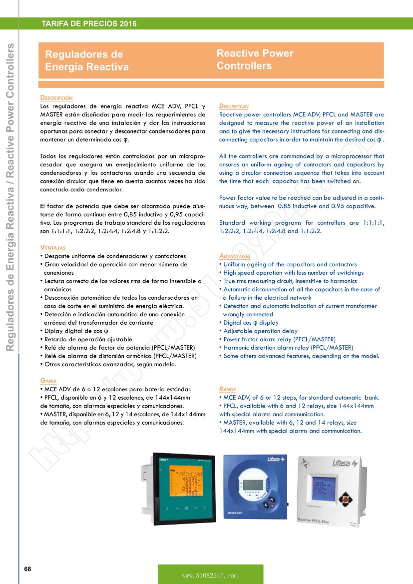
|
|
