|
FMLF (7%) POWER CAPACITOR FOR HARMONIC PROTECTION
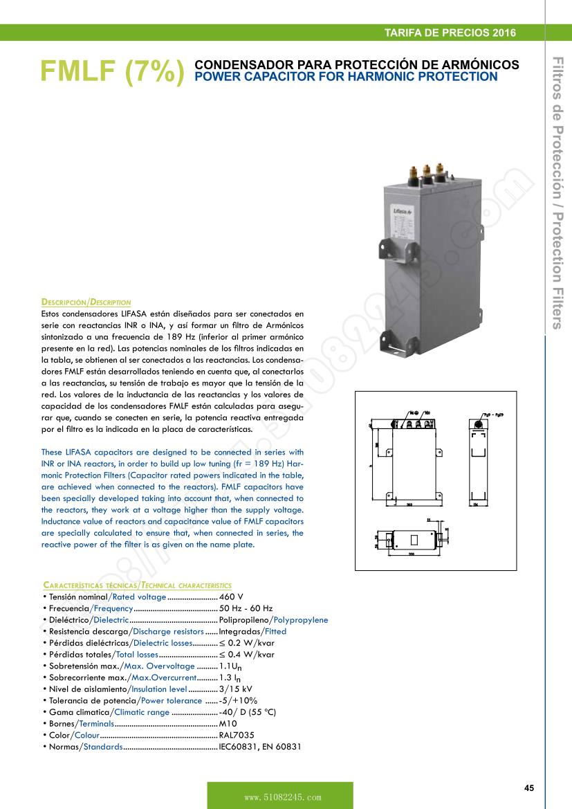
Description
These LIFASA capacitors are designed to be connected in series with INR or INA reactors, in order to build up low tuning (fr = 189 Hz) Harmonic Protection Filters (Capacitor rated powers indicated in the table, are achieved when connected to the reactors). FMLF capacitors have been specially developed taking into account that, when connected to the reactors, they work at a voltage higher than the supply voltage. Inductance value of reactors and capacitance value of FMLF capacitors
are specially calculated to ensure that, when connected in series, the reactive power of the filter is as given on the name plate.
Technical Characteristics
Tensi��n nominal/Rated voltage ........................460 V
Frecuencia/Frequency ........................................50 Hz - 60 Hz
Diel��ctrico/Dielectric ..........................................Polipropileno/Polypropylene
Resistencia descarga/Discharge resistors ......Integradas/Fitted
P��rdidas diel��ctricas/Dielectric losses ............�� 0.2 W/kvar
P��rdidas totales/Total losses ............................�� 0.4 W/kvar
Sobretensi��n max./Max. Overvoltage ..........1.1Un
Sobrecorriente max./Max.Overcurrent ..........1.3 In
Nivel de aislamiento/Insulation level ..............3/15 kV
Tolerancia de potencia/Power tolerance ......-5/+10%
Gama climatica/Climatic range ......................-40/ D (55 oC)
Bornes/Terminals .................................................M10
Color/Colour ........................................................RAL7035
Normas/Standards .............................................,
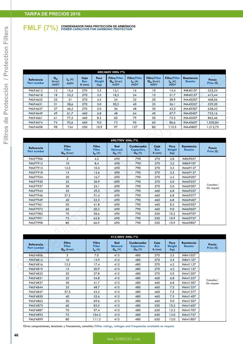
| 400/460V 50Hz 7% |
| Part number |
Qn (kvar)
460V |
In (A)
460V |
Box
h (mm) |
Weight
(kg) |
Filter
Qn (kvar)
440V |
/Filter
In (A)
440V |
Filter
Qn(kvar)
400V |
Filter
In (A)
400V |
Reactor |
Price (�) |
| FMLF4612 |
12 |
15,4 |
270 |
3.5 |
12,1 |
16 |
10 |
14.4 |
INR40107 |
325,24 |
| FMLF4618 |
18 |
23,2 |
270 |
3.5 |
18,2 |
24 |
15 |
21.7 |
INR40157 |
413,44 |
| FMLF4625 |
25 |
31 |
270 |
4.2 |
24 |
32 |
20 |
28.9 |
INA40207 |
468,56 |
| FMLF4631 |
31 |
38,6 |
270 |
5 |
30,3 |
40 |
25 |
36.1 |
INA40257 |
529,20 |
| FMLF4637 |
37 |
46,3 |
270 |
5 |
36 |
48 |
30 |
43.3 |
INA40307 |
628,43 |
| FMLF4649 |
49 |
61,7 |
460 |
6.8 |
48 |
64 |
40 |
57.7 |
INA40407 |
733,16 |
| FMLF4661 |
61 |
77,2 |
460 |
8.2 |
60 |
79 |
50 |
72.2 |
INA40507 |
865,46 |
| FMLF4674 |
74 |
92,6 |
460 |
9 |
73 |
95 |
60 |
86.6 |
INA40607 |
1.030,84 |
| FMLF4698 |
98 |
124 |
550 |
10.9 |
97 |
127 |
80 |
115.5 |
INA40807 |
1.212,75 |
|
|
|
|
|
|
|
|
|
|
|
|
|
|
|
|
|
|
|
|
|
|
| 690/790V 50Hz 7% |
|
|
| Part number |
Filter
Qn (kvar) |
Filter
In (A) |
Network
Un (V) |
Capacitors
Un (V) |
Box
h (mm) |
Weight
(kg) |
Reactor |
Price (�) |
|
|
| FMLF7906 |
5 |
4.2 |
690 |
790 |
270 |
2,8 |
INR69057 |
On
request |
|
|
| FMLF7912 |
10 |
8.4 |
690 |
790 |
270 |
3.5 |
INR69107 |
|
|
| FMLF7915 |
12.5 |
10.5 |
690 |
790 |
270 |
3.5 |
INA69127 |
|
|
| FMLF7918 |
15 |
12.6 |
690 |
790 |
270 |
3.5 |
INA69157 |
|
|
| FMLF7924 |
20 |
16.7 |
690 |
790 |
270 |
4.2 |
INA69207 |
|
|
| FMLF7930 |
25 |
20.9 |
690 |
790 |
270 |
5 |
INA69257 |
|
|
| FMLF7937 |
30 |
25.1 |
690 |
790 |
270 |
5 |
INA69307 |
|
|
| FMLF7943 |
35 |
29.3 |
690 |
790 |
460 |
6.8 |
INA69357 |
|
|
| FMLF7946 |
37.5 |
31.4 |
690 |
790 |
460 |
6.8 |
INA69377 |
|
|
| FMLF7949 |
40 |
33.5 |
690 |
790 |
460 |
6.8 |
INA69407 |
|
|
| FMLF7961 |
50 |
41.8 |
690 |
790 |
460 |
8.2 |
INA69507 |
|
|
| FMLF7973 |
60 |
50.2 |
690 |
790 |
460 |
9 |
INA69607 |
|
|
| FMLF7985 |
70 |
58.6 |
690 |
790 |
550 |
10.2 |
INA69707 |
|
|
| FMLF7991 |
75 |
62.8 |
690 |
790 |
550 |
10.9 |
INA69757 |
|
|
| FMLF7998 |
80 |
66.9 |
690 |
790 |
550 |
10.9 |
INA69807 |
|
|
|
|
|
|
|
|
|
|
|
|
|
|
|
|
|
|
|
|
|
|
|
|
| 415/480V 50Hz 7% |
|
|
| Part number |
Filter
Qn (kvar) |
Filter
In (A) |
Network
Un (V) |
Capacitors
Un (V) |
Box
h (mm) |
Weight
(kg) |
Reactor |
Price (�) |
|
|
| FMLF4806 |
5 |
7 |
415 |
480 |
270 |
3.5 |
INR41057 |
On
request |
|
|
| FMLF4812 |
10 |
13.9 |
415 |
480 |
270 |
3.5 |
INR41107 |
|
|
| FMLF4816 |
12.5 |
17.4 |
415 |
480 |
270 |
4.2 |
INA41127 |
|
|
| FMLF4819 |
15 |
20.9 |
415 |
480 |
270 |
4.2 |
INA41157 |
|
|
| FMLF4825 |
20 |
27.8 |
415 |
480 |
270 |
5 |
INA41207 |
|
|
| FMLF4831 |
25 |
34.8 |
415 |
480 |
460 |
6.8 |
INA41257 |
|
|
| FMLF4837 |
30 |
41.7 |
415 |
480 |
460 |
6.8 |
INA41307 |
|
|
| FMLF4844 |
35 |
48.7 |
415 |
480 |
460 |
7.5 |
INA41357 |
|
|
| FMLF4847 |
37.5 |
52.2 |
415 |
480 |
460 |
7.5 |
INA41377 |
|
|
| FMLF4850 |
40 |
55.6 |
415 |
480 |
460 |
7.5 |
INA41407 |
|
|
| FMLF4862 |
50 |
69.6 |
415 |
480 |
460 |
9 |
INA41507 |
|
|
| FMLF4875 |
60 |
83.5 |
415 |
480 |
550 |
10.2 |
INA41607 |
|
|
| FMLF4887 |
70 |
97.4 |
415 |
480 |
650 |
12.2 |
INA41707 |
|
|
| FMLF4893 |
75 |
104.3 |
415 |
480 |
650 |
13 |
INA41757 |
|
|
| FMLF4899 |
80 |
111.3 |
415 |
480 |
650 |
13 |
INA41807 |
|
|
Other ratings, voltages and frequencies available on request.
Static Capacitor Banks
DESCRIPTION
Traditional reactive power compensation equipment with electromechanical contactors, has a well proven performance in installations where the load has, slow variations and it is not very sensitive to voltage fluctuations. Today, however, more and more industrial installations include electronic equipment very sensitive to voltage variations (PLC, computers, etc.) And also very fast changing working cycles (automatic welding machines, robots, etc.).
Reactive power compensation with static contactors offers the best answer to these new industry requirements.
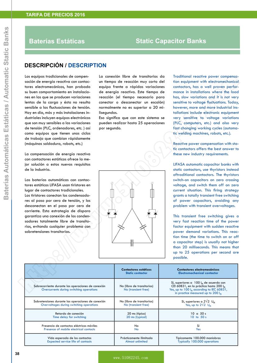
LIFASA automatic capacitor banks with static contactors, use thyristors instead of traditional contactors. The thyristors switch-on capacitors on zero crossing voltage, and switch them off on zero current situation.
This firing strategy grants a totally transient free switching of power capacitors, avoiding any problem with transient overvoltages.
This transient free switching gives a very fast reaction time of the power factor equipment with sudden reactive power demand variations. This reaction time (the time to switch on or off a capacitor step) is usually not higher than 20 milliseconds. This means that up to 25 operations per second are possible.
GENERAL CHARACTERISTICS
LIFASA automatic capacitor banks with static contactors are supplied completely assembled and ready for use: it is only necessary to give them the operation signal from a suitable current transformer, and to connect them to the mains by cables of adequated section. They are composed of the following elements:
Reactive power Controller
These banks use the MCE-F controllers, that are a fast response variation of the MCE series of controllers. These controllers are specially designed for the control of thyristor capacitor banks and are characterized by their optically isolated outputs and also for having an extremely fast response time that can be up to 20 milliseconds.
Control Module
It is formed by an electronic control circuit, that gives the firing pulses to the thyristors to switch on at zero voltage point and to switch off at zero current situation. The control module is assembled on a printed circuit board and receives the action signal from the MCE controller.
Power Module
It is formed by three pairs of thyristors in anti-parallel connection, mounted and assembled on well dimensioned heat sinks, protection fuses and limiting inductances.
Capacitors
These banks use the six terminal versions of FILMETAL and MINIFILMETAL series of power capacitors.
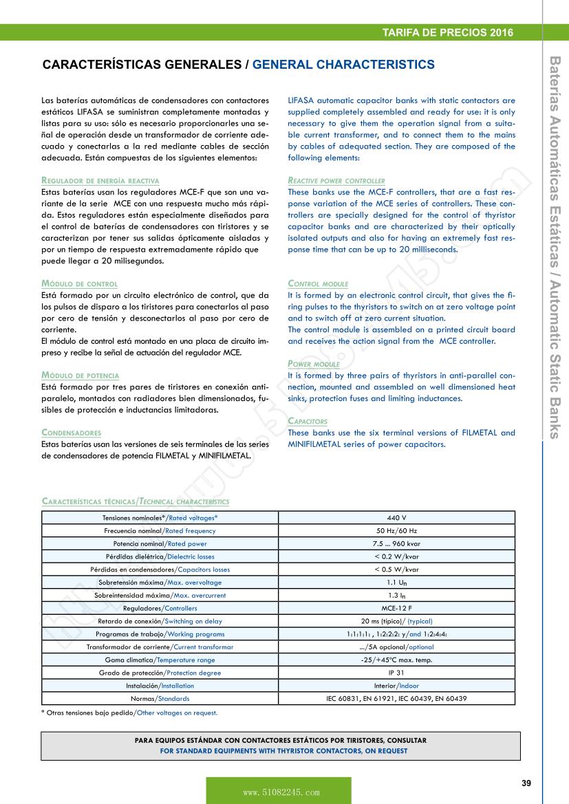
Technical Characteristics
|
Rated voltages |
440V |
Rated frequency |
50 Hz/60 Hz |
Rated power |
7.5 ... 960 kvar |
Dielectric losses |
< 0.2 W/kvar |
Capacitors losses |
< 0.5 W/kvar |
Maximum overvoltage |
1.1 Un |
Maximum overcurrent |
1.3 In |
Controllers |
MCE-12 F |
Switching on delay |
20 ms (typical) |
Working programs |
1:1:1:1 / 1:2:2:2 / 1:2:4:4 |
Current transformer |
... /5 (Optional) |
Temperature range |
-25oC/+45 oC max. temp. |
Degree of protection |
|
Installation |
Indoor |
Standards |
, , , |
Other voltages on request.
Protection Filters
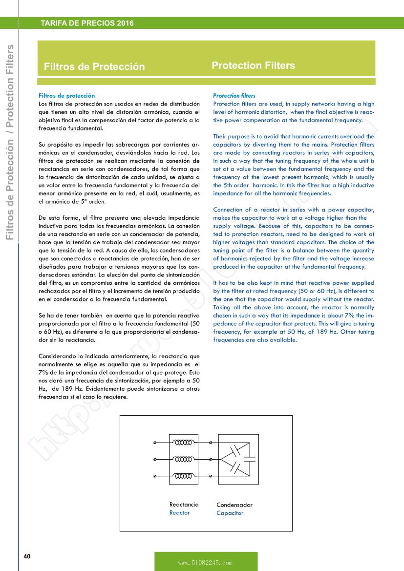
Protection filters
Protection filters are used, in supply networks having a high level of harmonic distortion, when the final objective is reactive power compensation at the fundamental frequency.
Their purpose is to avoid that harmonic currents overload the capacitors by diverting them to the mains. Protection filters are made by connecting reactors in series with capacitors, in such a way that the tuning frequency of the whole unit is set at a value between the fundamental frequency and the frequency of the lowest present harmonic, which is usually the 5th order harmonic. In this the filter has a high inductive impedance for all the harmonic frequencies.
Connection of a reactor in series with a power capacitor, makes the capacitor to work at a voltage higher than the supply voltage. Because of this, capacitors to be connected to protection reactors, need to be designed to work at higher voltages than standard capacitors. The choice of the tuning point of the filter is a balance between the quantity of harmonics rejected by the filter and the voltage increase produced in the capacitor at the fundamental frequency.
It has to be also kept in mind that reactive power supplied by the filter at rated frequency (50 or 60 Hz), is different to the one that the capacitor would supply without the reactor.
Taking all the above into account, the reactor is normally chosen in such a way that its impedance is about 7% the impedance of the capacitor that protects. This will give a tuning frequency, for example at 50 Hz, of 189 Hz. Other tuning frequencies are also available. |
|
Capacitor FMLF
FMLF4612 FMLF7973
FMLF4618 FMLF7985
FMLF4625 FMLF7991
FMLF4631 FMLF7998
FMLF4637 FMLF4806
FMLF4649 FMLF4812
FMLF4661 FMLF4816
FMLF4674 FMLF4819
FMLF4698 FMLF4825
FMLF7906 FMLF4831
FMLF7912 FMLF4837
FMLF7915 FMLF4844
FMLF7918 FMLF4847
FMLF7924 FMLF4850
FMLF7930 FMLF4862
FMLF7937 FMLF4875
FMLF7943 FMLF4887
FMLF7946 FMLF4893
FMLF7949 FMLF4899
FMLF7961
|
